|
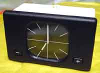
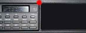
Second step is to remove your old clock - To do this, remove
the radio and the radio's mounting case and then reach inside
the vacant radio slot at the side next to the clock, at the
top you should feel a little lever (position marked by red
dot on remove_clock.jpg) which you need to press (push it
towards the engine) and the mechanism should make the clock
move out towards you and you can then pull it out the rest
of the way with your fingers.
The third step is to try the OBC to see if it works - The
connector is clipped into the back of the mounting frame,
unclip this and pull it out a bit (there should be an inch
or two give in the wiring) and then plug it into the back
of the OBC. Turn the ignition on and see if the OBC comes
to life.

Clock removed
If the OBC doesn't come up the next step is to figure out
why. The list of connections is given in the table below so
start by checking that there is +12v at pins 6, 8, 9 &
17. The most likely culprit is pin 17 as there will be no
power to this if your car doesn't have the auxiliary horn
relay installed and without power at pin 17 the OBC will play
completely dead. If there is no power at pin 17 an easy solution
is to cut the red-grey-yellow wire that goes to pin 17, cut
it as far from the connector as possible to make life easier,
and join this to the red-yellow (red with a yellow stripe,
there's also a yellow wire with a red stripe!) wire that provides
power to pin 9. You could join these via a 5 or 10 amp fuse
if you prefer and it may be no harm to tape off the end of
the red-grey-yellow wire coming from the car so it can't cause
any problems.
Digital clock/temperature indicator
---
pin4: ground
pin5: blue/red/yellow, temp sensor
pin8: + from fuse F1
pin9: + from fuse F20
pin18: white/blue, chimes
pin19: white/red, chimes
pin22: grey/red, light switch
OBC
---
pin1: violet/green/yellow, alarm system
pin10: black/green, starter
pin6: + from fuse F17
pin9: + from fuse F20 (red/yellow)
pin8: + from fuse F1
pin22: grey/red, light switch
pin25: yellow/red, turn signal switch
pin3: white/yellow, diagnostics
pin16: white/violet, diagnostics
pin14: white/grey, instrument cluster
pin7: black/white, instrument cluster
pin4: ground
pin5: blue/red/yellow, temp sensor
pin20: black/red/yellow, pre-ventilation
pin21: black/white, pre-ventilation
pin23: violet/white/yellow, alarm system
pin17: red/grey/yellow, alarm system
pin26: black/red/yellow, fuel tank level sensor
pin12: brown/violet, fuel tank level sensor
pin11: white/black, DME
pin24: black/violet, DME
pin19: white/red, chimes
pin18: white/blue, chimes
pin15: white/brown, radio
pin2: blue/brown/yellow, radio
Once the OBC is working, the next step is make it fit properly
- You can either replace the mounting frame with the one designed
to hold the OBC or alternatively you can cut away the plastic
at the back of the original mounting frame (This can even
be done without removing the mounting frame if you are careful
by using a suitable saw from the front) so that the OBC will
slide in all the way until the front of it is flush with the
console.

Next, you need to set the country setting for language, miles/km,
C/F and l/100Km / Km/l. - To do this you need to access the
OBC test menu by simultaneously pressing the 1000 and 10 keys
so that the display changes to "TEST". With the
10 & 1 keys enter 11 on the display and then press the
S/R button. "0 LAND" should now be on the display
and you can alter this by using the 1000 & 100 keys and
the S/R to save. The settings are from "0 LAND"
to "9 LAND" and through trial and error you should
be able to find the setting that is best for you. Also, some
settings use US gallons while others use European gallons
so take that into account.
If the OBC appears to be reporting inaccurate fuel consumption
figures it can be calibrated to give the correct values. -
Fill the fuel tank to the maximum and reset the trip counter
and one of the OBC's average fuel consumption monitors. Run
the fuel tank nearly empty and fill the fuel tank again to
the maximum. The amount of fuel it now takes to fill the tank
is the amount used to cover the distance recorded on the trip
meter so, from this, work out the actual fuel consumption
of the car and then compare this to what the OBC reported
as the average fuel consumption. If these two average fuel
consumption figures are not exactly the same then you need
to calibrate the OBC by entering a new correction factor.
The fuel consumption correction factor is a locked function
of the OBC so before you can access it, you must first unlock
the OBC - Access the OBC test menu by simultaneously pressing
the 1000 and 10 keys so that the display changes to "TEST".
With the 10 & 1 keys enter 19 on the display and then
press the S/R button. Add the current day and month (as it
is known to the OBC) and enter this value and then press the
S/R button, the OBC should now be unlocked. To access the
fuel consumption calibration factor you once more need to
simultaneously press the 1000 and 10 keys so that the display
changes to "TEST". With the 10 & 1 keys enter
20 (Be careful not to enter 21 as this will reset the OBC)
on the display and then press the S/R button - you should
now see something like 1000 CORR, this is your current correction
factor. To calculate your new correction factor use the following:
new_correction_factor = old_correction_factor * actual_mpg
/ obc_mpg
Enter your new correction factor into the OBC using the 1000/100/10/1
keys and then press the S/R button. If you want to relock
the OBC - enter function 19 again then press the C/F button
to lock.
Much of the information contained above came from internet
posts by: Priit Varik, Mark M and Al and from http://home.iae.nl/users/bts/obc.htm
More info from Mark about temperature sensor:
I have a 1990 E34 525iA SE (UK spec) that was originally
fitted with an analogue clock. Following your instructions
I removed the clock and fitted a used OBC. This worked fine,
but had the annoying problem of sounding the gong every time
the ignition was switched on due to the external temperature
sensor not being fitted.
Well, after a while this just because too much, to after
some investigation I found that the wiring harness for the
temperature sensor was indeed fitted to the car. It was located
behind the radiator in the same place where the horn is mounted,
i.e. in the centre of the car, behind the grill in between
the lights. The wiring harness was coiled up and clipped out
of the way. Once I had released the clip, it was then just
a simple case of plugging in my new temperature sensor to
the harness and it worked first time. I did try to route the
sensor somewhere away from the radiator so it would measure
the
external temperature, not the radiator temperature !
The only trick that the old girl had left was that it seems
to take a few hours for the OBC to register the correct temperature.
It crept slowly up from -39oC to the correct outside temperature.
I'm assuming that there must be some kind of digital or analogue
filter on the system that has a very large time constant.
Anyway, once it had reached correct temperature it seems to
operate correctly, agreeing with roadside temperature signs.
More temperature sensor from Mark A.
I finally got bored with the display telling me it was -34
outside, so I ordered the temp sensor from BMW main dealer
for only 17 pounds UK.
Took the front off the car & spent hours searching for
the magic wire to connect it up. Needless to say, it wasn't
there. It would seem that mine (94 525 European spec) didn't
have it fitted. The solution is to run a wire from one side
of the sensor to earth (ground) & the other one thru the
car & splice it in to pin 5. All now works ok.
Just thought this may be useful to anyone else doing the retrofit
& thinking they're going mad as the cant find the missing
wire.
More info from Andy:
The OBC will chime every time you turn on the ignition and
give you a -34 degrees warning if you don't have or fit a
temperature sensor. I thought mine had a fault until I searched
a few sites.
More info from Martin M.
The user should check the wiring loom into the back of
the clock. If it has a 'bunch' of wires then your ok, if it
contains only three wires (as is the case withe my E34) then
it is not possible.
More info from Tom Bosman:
Having just retrofitted an OBC to an 89 525i (thanks to your
notes) I would like to pass on a little additional info re
a problem I encountered.
As part of the retrofit I also purchased an indicator stalk
(turn signal) with switch. When I pulled the old one out and
compared it with the new one there were a few differences
(besides the extra wires for switch). The old switch had a
relay attached to the 12 pin plug which strangely had no output.
One of the wires of this relay was on the same pin as the
yellow/red wire on the new switch which operates the dash
display from OBC. After trying the switch as is and it not
working I then wired it up the same as the old switch and
then had a yellow/red wire floating free. After some further
investigation I discovered another connector under the socket
for indicator stalk connection which had a yellow/red. I traced
this wire back to pin 25 of OBC which is the trigger for dash
display. After connecting my spare yellow/red to this the
dash display now worked. I also discovered that the relay
with no output was merely connected to the flasher to make
it audible. Without the relay the flashers worked perfectly
but were silent. Hope this can be of help to some others who
have trouble with indicator stalk switch.
|


